Ukraine · People · Solutions · Engineering · Digital

NGB / DRILLING EQUIPMENT

Reliable equipment.
Consistent drilling progress.

Equipment readiness sets the pace of well construction. Our own fleet, disciplined maintenance and accountability for every component support safe operations and fewer unplanned shutdowns.

Our target: zero equipment-related NPT.

Working ahead of failure through preventive maintenance, condition checks and timely service. NPT means non-productive time.

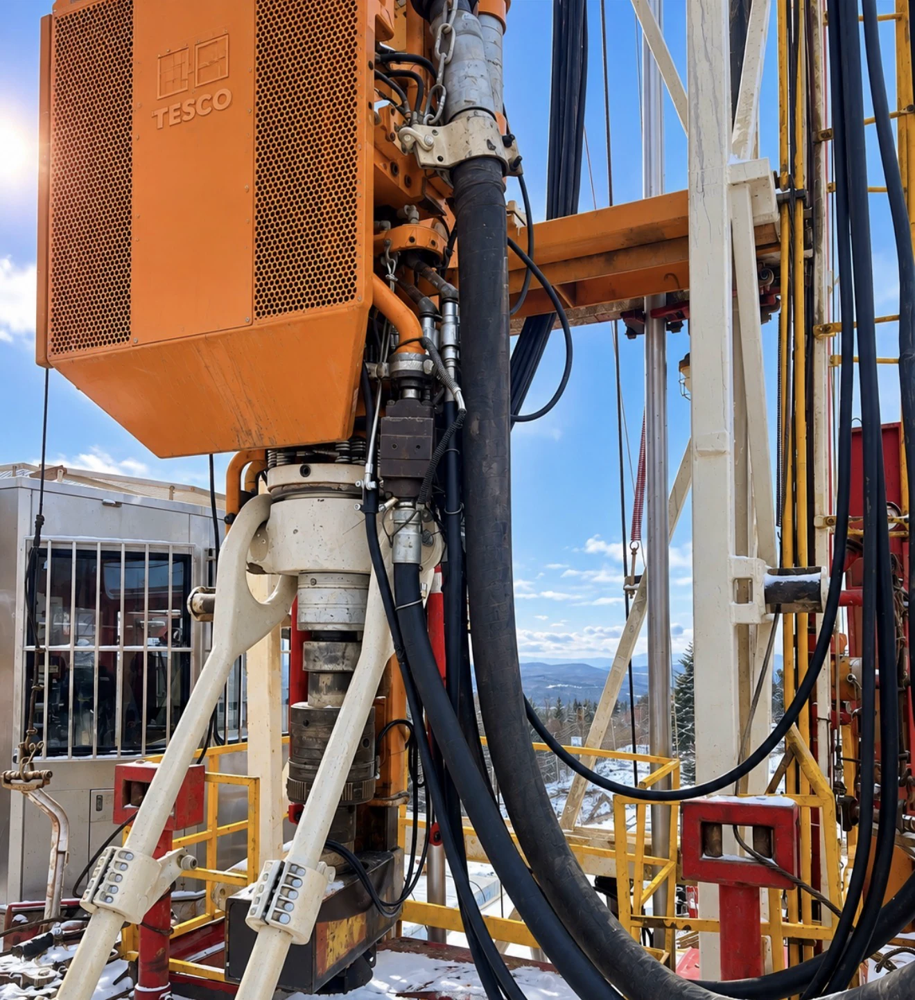
Top drive system on a drilling rig
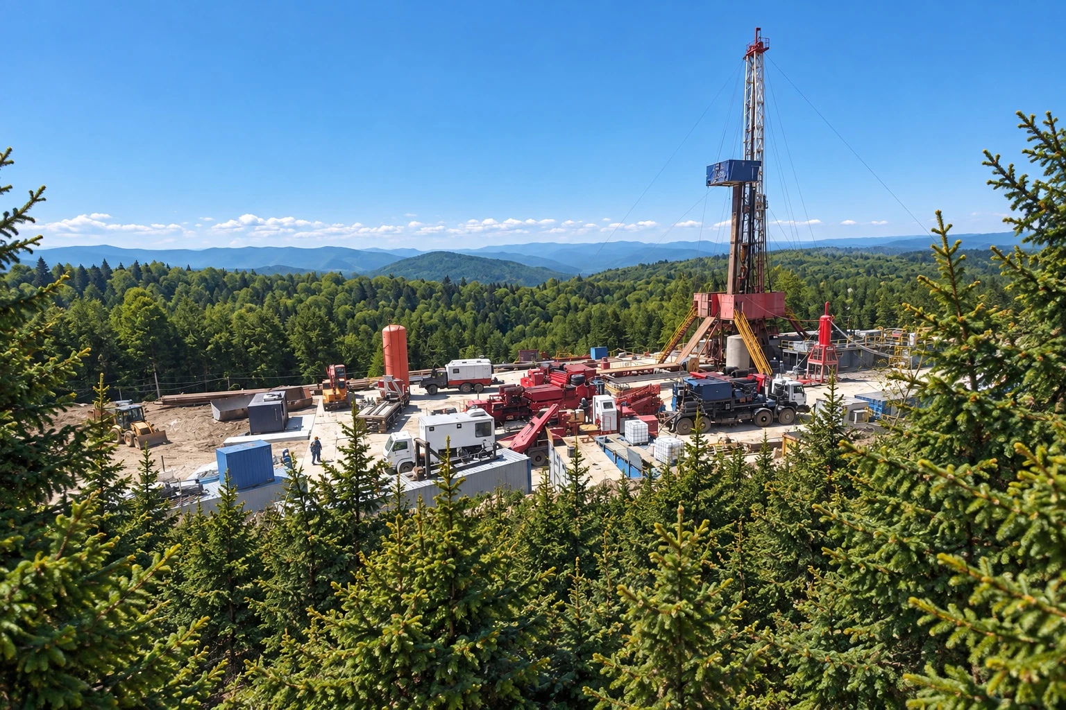
Visualisation of a drilling rig in a forest landscape
Visualisation of a drilling site.

Reliability starts with the way equipment is operated.

At NGB, owning equipment means taking responsibility for its technical condition. Our priorities are people’s safety, equipment readiness for operating loads and reducing the risk of unplanned shutdowns.

We combine preventive maintenance with manufacturer recommendations and checks of actual component condition. High technical standards depend on daily discipline, traceable work and sound decisions by our mechanical team.

The principles behind our equipment readiness.

Preventive maintenance and service history

Maintenance records capture inspections, operating hours, completed work, component replacements and upcoming service intervals. A consistent history for each asset supports service-life management and timely technical decisions.

An accountable mechanical team

Qualified personnel carry out daily condition checks, plan maintenance and verify readiness for operation. Repair quality, correct installation and post-service checks form one continuous process.

Authorised service

Specialist maintenance and repairs are entrusted exclusively to official dealers and manufacturer-authorised service partners with verified competence and the required certification.

Genuine components

We use genuine spare parts and manufacturer-recommended consumables with verified provenance. Counterfeit components and parts of unknown origin are unacceptable.

Operating experience drives improvement.

We develop our specialists’ competence, refine technical procedures and apply lessons from equipment operation. Accountability extends to every asset we bring to a project.

TECHNICAL SPECIFICATIONS

ZJ40 drilling rig and principal equipment.

Equipment configuration, models and parameters — from hoisting systems and the top drive to mud pumps and the circulating system.

KEY EQUIPMENT

TOP DRIVE TDS-500

Top drive system with an electric AC drive.

Full top drive specification
Nominal load capacity
225t
Motor power
500kW
Nominal torque
50kN·m
Maximum torque
65kN·m
Maximum speed
250rpm

PLC with touchscreen. Full telemetry: torque, speed and load.

Main equipment: models and specifications

A short list of the principal units. Each item links to its section in the complete specification table.

Equipment Model / type Key specifications
01TOP DRIVEDetailed specification

TDS-500

Nominal load capacity: 225 t.

Electric AC drive; 500 kW motor.

Torque: 50 kN·m nominal / 65 kN·m maximum.

Maximum speed: 250 rpm.

PLC with touchscreen; torque, speed and load telemetry.

02Drilling rigDetailed specification

ZJ40

Manufacturer: DFXK NAFTOMASH LLC.

Mobile rig. Permissible hook load: not less than 225 t.

Nominal drilling depth: not less than 4,000 m.

Power: 1,000 hp; circulation system volume: 280 m³.

03DrawworksDetailed specification

JC40DBL-1000-225

Drive power: 1,000 hp; hook load: 225 t.

5 speeds; drilling line diameter: 32 mm.

04Mud pumpDetailed specification

F-1300

Rated power in the specification: 1,000 hp; 3 cylinders.

Maximum working pressure: 34.5 MPa.

Maximum flow: 1,250 L/min at Ø180 mm / 1,450 L/min at Ø200 mm.

05Rotary tableDetailed specification

RTSL-500

Maximum torque: 48 kN·m; maximum speed: 300 rpm.

Table internal diameter: 500 mm; mechanical drive.

06Hoisting systemDetailed specification

DG225-6×6

Crown block

TG225-6×6

Travelling block

Y225

Hook

Nominal load of each unit: 225 t.

Crown and travelling blocks: 6 sheaves each, Ø762 mm; Ø32 mm line.

Hook: automatic locking device with spring latch.

07MastDetailed specification

Model not specified in the source.

Mast height: 36 m; useful height: 32 m.

Maximum static hook load: not less than 225 t.

Permissible wind speed: 38.6 m/s.

08SubstructureDetailed specification

DZ225CX11

Maximum load: 225 t; height: 9 m.

Hydraulic lifting system; 4 hydraulic jacks.

09Drilling lineDetailed specification

6×36WS-IWRC-1770

Diameter: 32 mm; working length: 4,000 m.

Breaking load: not less than 565 kN; minimum safety factor: 5:1.

10Mud systemDetailed specification

Mud Circulating System

System type stated in the source.

Total volume: 280 m³; 4 sections; 8 agitators, 7.5 kW each.

2 shakers; shaker throughput: 160 m³/h.

Vacuum degasser: 240 m³/h; centrifuge: 40 m³/h.

11Standpipe manifoldDetailed specification

Stand Pipe Manifold

Equipment type stated in the source.

Working pressure: 35 MPa nominal / 40 MPa maximum.

Bore: 76 mm (3″); outlets: 2–3.

12Power supplyDetailed specification

Perkins / Cummins

Makes stated in the source; exact models are not specified.

Main generator: 600 kW; backup: 300 kW.

1 generator of each type; 400/230 V, 50 Hz.

13Pneumatic systemDetailed specification

Electric screw compressor; model not specified.

Capacity: 6 m³/min; working pressure: 0.8 MPa.

Receiver capacity: 1,000 L.

Models and ratings are taken from the source specification. Where an exact model is absent, this is stated; a type or make has not been replaced with an invented model.

The complete inventory, individual system parameters and auxiliary equipment are available in the second tab.

Open the full table

Full specification

Download DOCX
01

General specifications

16 entries

Scroll sideways to view all columns.

No. Equipment Unit Technical specification
1 Type – ZJ40 mobile drilling rig
2 Year of manufacture, not earlier than Year 2016
3 Manufacturer – DFXK NAFTOMASH LLC
4 Permissible hook load, minimum Metric tonne 225 t
5 Rig power hp 1000
6 Nominal drilling depth, minimum m 4000
7 Circulating system volume m³ 280
8 Rig electrical equipment (applicable standard) – API Spec 7K
9 Rig earthing system (applicable standard and technical specifications) – API Spec 7K, DSTU EN 16228-1:2016 (EN 16228-1:2014, idt)
10 Rig lighting °C From –20 to +55
11 Operating temperature range °C From –20 to +55
12 Weight of the heaviest assembly Metric tonne 48 t
13 Number of truckloads pcs 8 truckloads (according to the equipment data sheet)
14 Current location (nearest settlement, country) – Ukraine
15 Foundation type for mast and drilling equipment – Reinforced concrete slabs
16 Site dimensions for rig and crew camp m 120 × 144
02

Mast

24 entries

Scroll sideways to view all columns.

No. Equipment Unit Technical specification
1Main technical specifications
1.1 Applicable standard and technical specifications – API Spec 4F
1.2 Maximum static hook load, minimum Metric tonne 225
1.3 Overall height, including substructure m 39
1.4 Mast height m 36
1.5 Usable mast height m 32
1.6 Permissible wind speed m/s 38,6
1.7 Operating temperature range °C From –19 to +50
2Mast equipment
2.1 Derrickman’s platform set Included
2.2 Height adjustment above the rig floor (intervals) m 20,8; 23,8; 28,8
2.3 Drill-collar handling mechanism at the derrickman’s platform (jacking winch) t 1
2.4 Derrickman’s platform pipe-racking capacity stands 4000 m – Ø4½″; 3500 m – Ø5½″
2.5 Windproof wall panels set Included
2.6 Attachment for the derrickman’s emergency escape system – Height 2.6 m
2.7 Equipment maintenance platforms set Included
2.8 Stairs and caged ladders set Included
2.9 Equipment set for raising the mast, substructure and drawworks – Not used
2.10 Deadline stabiliser set Included
2.11 Fast-line guard (stabiliser) set Included
2.12 Mast standpipe set 4″
2.13 Gate valves – Z23Y100–35 MPa
2.14 Safety components set Included
2.15 Wind dampers set Included
2.16 Crown-block warning lights – Included
2.17 Counterweight system set Included
03

Substructure

30 entries

Scroll sideways to view all columns.

No. Equipment Unit Technical specification
1Main technical specifications
1.1 Type – DZ225CX11
1.2 Applicable standard and technical specifications – API Spec 4F
1.3 Maximum load t 225
1.4 Substructure height m 9
1.5 Structural weight t 50
1.6 Construction material – Q345B steel
1.7 Number of sections pcs 2
1.8 Section length m 9 / 4,5
1.9 Operating temperature range °C From –19 to +50
1.10 Hydraulic substructure lifting system availability – Included
1.11 Drive type for the hydraulic substructure lifting system – Hydraulic
1.12 Substructure locking system during lifting – Mechanical
1.13 Transition platform design between substructure and rig – All-metal
2Additional substructure equipment
2.1 Substructure lifting system set Included
2.2 Hydraulic jacks pcs 4
2.3 Hydraulic power unit for jack control set Included
2.4 Wellhead maintenance platforms – Included
2.5 Hatch or stairs for wellhead access – Included
2.6 Height-adjustable substructure supports – Included
2.7 Floor decking – Removable metal decking
2.8 Fastener set – Complete
2.9 Earthing system – Included
2.10 Work-area lighting – Included
2.11 Personnel evacuation system – Included
2.12 Safety barriers – Included
2.13 Anti-corrosion coating components – Included
2.14 Drill-string weight sensor – Model ZJ-225-W
2.15 Load indication system – Included (analogue and digital)
2.16 Power and signal cables – Included in the set
2.17 Hydraulic power unit heating system – Included
04

Crown block

26 entries

Scroll sideways to view all columns.

No. Equipment Unit Technical specification
1Main technical specifications
1.1 Type – DG225-6×6
1.2 Applicable standard and technical specifications – API Spec 8A / 8C
1.3 Rated load t 225
1.4 Number of line parts pcs 6
1.5 Line diameter mm 32
1.6 Number of sheaves pcs 6
1.7 Sheave diameter mm 762
1.8 Bearing type – Tapered roller bearings
1.9 Housing material – 42CrMo steel
1.10 Crown-block weight t 6,3
1.11 Operating temperature range °C From –19 to +50
1.12 Lubrication system – Centralised, automatic
1.13 Reeving arrangement – 6×6
1.14 Load on the rotation axis kN 2205
1.15 Condition-monitoring components – Visual inspection windows
1.16 Travelling-block travel limiter – Included (mechanical stop)
2Crown-block equipment
2.1 Sheave assembly set Included
2.2 Housing with guides set Included
2.3 Mounting shaft set Included
2.4 Suspension bracket set Included
2.5 Sheaves with bearings set 6
2.6 Protective covers set Included
2.7 Centralised lubrication system set Included
2.8 High-strength bolted connections set Included
2.9 Equipment data sheet and certificate of conformity – Included
2.10 Crown-block lifting hook – Included
05

Travelling block

28 entries

Scroll sideways to view all columns.

No. Equipment Unit Technical specification
1Main technical specifications
1.1 Type – TG225-6×6
1.2 Applicable standard and technical specifications – API Spec 8A / 8C
1.3 Rated load t 225
1.4 Number of sheaves pcs 6
1.5 Sheave diameter mm 762
1.6 Line diameter mm 32
1.7 Reeving arrangement – 6×6
1.8 Bearing type – Tapered roller bearings
1.9 Hook suspension type – Slings with eyes
1.10 Shaft type – Removable
1.11 Housing material – 42CrMo steel
1.12 Travelling-block weight t 7,8
1.13 Operating temperature range °C From –19 to +50
1.14 Lubrication system – Centralised, automatic
1.15 Travel limiting system – Included (mechanical)
1.16 Line-retaining device during spooling – Included
1.17 Load on the rotation axis kN 2205
1.18 Efficiency factor % 98
2Travelling-block equipment
2.1 Travelling-block housing set Included
2.2 Sheaves with bearing assemblies set 6
2.3 Shafts with retainers set Included
2.4 Suspension hooks set Included
2.5 API-certified slings set Included
2.6 Centralised lubrication system set Included
2.7 High-strength bolted connections set Included
2.8 Equipment data sheet and certificate of conformity – Included
2.9 Condition-monitoring system – Visual inspection windows
2.10 Transport fittings (removable lifting eyes) – Included
06

Hook

28 entries

Scroll sideways to view all columns.

No. Equipment Unit Technical specification
1Main technical specifications
1.1 Type – Y225
1.2 Applicable standard and technical specifications – API Spec 8A / 8C
1.3 Rated load t 225
1.4 Design – One-piece housing with sling suspension
1.5 Connection type – API-threaded or travelling-block connection
1.6 Own weight t 2,5
1.7 Assembled hook height mm 2360
1.8 Hook rotation angle about its axis degrees 360
1.9 Bearing assembly type – Combined (radial-thrust)
1.10 Load on the bearing assembly kN 2205
1.11 Hook locking device type – Automatic (spring lock)
1.12 Housing design – Forged steel, heat-treated
1.13 Material – 42CrMo steel
1.14 Coating – Anti-corrosion polyurethane paint
1.15 Operating temperature range °C From –19 to +50
1.16 Lubrication – Through grease nipples
1.17 Self-opening prevention mechanism – Included
1.18 Anti-sway mechanism – Included
1.19 Raised-position locking device – Included
1.20 Equipment data sheet and API certificate – Included
2Hook equipment
2.1 Hook body with swivel head set Included
2.2 Complete bearing assembly set Included
2.3 Locking mechanism with retainer set Included
2.4 Self-opening prevention device set Included
2.5 Grease nipples pcs 2
2.6 Gasket and seal set set Included
2.7 High-strength bolts and split pins set Included
2.8 Equipment data sheet and certificate of conformity – Included
07

Drawworks

37 entries

Scroll sideways to view all columns.

No. Equipment Unit Technical specification
1Main technical specifications
1.1 Type – JC40DBL-1000-225
1.2 Applicable standard and technical specifications – API Spec 7K
1.3 Rated hook load t 225
1.4 Drive power hp 1000
1.5 Number of speeds pcs 5
1.6 Drum diameter mm 610
1.7 Drum width mm 410
1.8 Line diameter mm 32
1.9 Drum capacity m 800
1.10 Maximum lowering speed under load m/s 1,2
1.11 Maximum unloaded hoisting speed m/s 1,8
1.12 Gearbox transmission ratio – 17,3:1
1.13 Main brake type – Band, double-band
1.14 Main brake torque kN·m 30
1.15 Auxiliary brake type – Electromagnetic or water brake
1.16 Auxiliary brake torque kN·m 25
1.17 Brake control – Pneumohydraulic
1.18 Clutch type – Pneumatic, friction
1.19 Number of clutches pcs 4
1.20 Gearbox type – Planetary, three-stage
1.21 Lubrication system – Centralised, forced
1.22 Gearbox cooling – Forced oil cooling
1.23 Operating noise level dB ≤85
1.24 Drawworks weight t 38
1.25 Operating temperature range °C From –19 to +50
2Drawworks equipment
2.1 Drawworks housing set Included
2.2 Drum with pulley set Included
2.3 Planetary gearbox set Included
2.4 Main brake set Included
2.5 Auxiliary brake set Included
2.6 Pneumatic clutches set Included
2.7 Brake control system set Included
2.8 Lubrication system with pump set Included
2.9 Water or air cooling – Included
2.10 Protective guards and safety components – Included
2.11 Instrumentation set – Included
2.12 Equipment data sheet and certificate of conformity – Included
08

Drilling line

26 entries

Scroll sideways to view all columns.

No. Equipment Unit Technical specification
1Main technical specifications
1.1 Type – 6×36WS-IWRC-1770
1.2 Applicable standard and technical specifications – API Spec 9A, ISO 2408
1.3 Line diameter mm 32
1.4 Line construction – 6 strands of 36 Warrington-Seale wires with an IWRC steel core
1.5 Number of wires in the line pcs 216
1.6 Wire material – High-strength steel, 1770 MPa
1.7 Breaking load, minimum kN 565
1.8 Minimum safety factor – 5:1
1.9 External coating – Anti-corrosion, type A lubricating coating
1.10 Lubricant type – Grease, water-resistant and frost-resistant
1.11 Line flexibility – High (“Flexible” category)
1.12 Lay direction – Right-hand, regular (Z-Lay)
1.13 Core diameter (IWRC) mm 13
1.14 Weight per metre of line kg 4,34
1.15 Working line length m 4000
1.16 Operating temperature range °C From –40 to +50
1.17 Certification – API Monogram, ISO 9001
1.18 Corrosion resistance class – C2 (enhanced)
1.19 Warranty period months 12
1.20 Recommended storage period months 24
2Drilling-line equipment
2.1 Line coil set Included (1 coil × 4000 m)
2.2 DIN 741 wire-rope clips pcs 30
2.3 Reinforced steel thimbles pcs 6
2.4 Line-end fittings (hook, shackle) set Included
2.5 Marking set and quality certificate – Included
2.6 Maintenance lubricant set – Included
09

Slings

26 entries

Scroll sideways to view all columns.

No. Equipment Unit Technical specification
1Main technical specifications
1.1 Type – Wire-rope slings with reinforced thimbles
1.2 Applicable standard and technical specifications – API Spec 8C, ISO 7531
1.3 Wire-rope material – High-strength steel, 1770 MPa
1.4 Line construction – 6×36WS-IWRC
1.5 Line diameter mm 32
1.6 Sling length m 12
1.7 Rated load t 225
1.8 Breaking load kN 565
1.9 Thimble type – Reinforced, forged steel
1.10 Swaging method – Aluminium ferrule swaging
1.11 Coating type – Anti-corrosion, lubricating
1.12 Suspension type – For suspending the travelling block from the crown block
1.13 Weight of one sling kg 45
1.14 Number of slings per set pcs 2
1.15 Operating temperature range °C From –40 to +50
1.16 Certification – API Monogram, ISO 9001
1.17 Safety class – Conforms to group G4
1.18 Safety factor – 5:1
1.19 Warranty period months 12
1.20 Recommended storage period months 24
2Sling equipment
2.1 Wire-rope sling with thimbles set Included (2 pcs)
2.2 Reinforced thimbles pcs 4
2.3 Swaging ferrules pcs 2
2.4 Certificates and equipment data sheets – Included
2.5 Identification tags – Included
2.6 Storage and transport set – Included (wooden container)
10

Rotary table

29 entries

Scroll sideways to view all columns.

No. Equipment Unit Technical specification
1Main technical specifications
1.1 Type – RTSL-500
1.2 Applicable standard and technical specifications – API Spec 7K
1.3 Maximum static load moment kN·m 50
1.4 Maximum torque kN·m 48
1.5 Maximum table speed rpm 300
1.6 Table internal diameter mm 500
1.7 Rotary-pin seating diameter mm 445
1.8 Drive type – Mechanical, via cardan drive
1.9 Gearbox type – Planetary
1.10 Lubrication system – Forced, with filtration
1.11 Brake type – Mechanical disc brake
1.12 Cooling system – Oil, natural circulation
1.13 Housing material – Cast 42CrMo steel
1.14 Rotary-table material – 35CrMo steel, heat-treated
1.15 Bearing assembly – Radial-thrust roller bearings
1.16 Rotary axis inclination angle degrees 0
1.17 Rotary-table weight t 9,5
1.18 Operating temperature range °C From –19 to +50
1.19 Electric-drive explosion protection class – Ex d IIB T4
1.20 Rotary-table housing earthing – Included
2Rotary-table equipment
2.1 Rotary-table housing set Included
2.2 Complete rotary table set Included
2.3 Planetary gearbox set Included
2.4 Cardan drive set Included
2.5 Lubrication system with filter set Included
2.6 Braking system set Included
2.7 Instrumentation set – Included
2.8 Protective guards – Included
2.9 Equipment data sheet and API certificate of conformity – Included
11

Top drive

33 entries

Scroll sideways to view all columns.

No. Equipment Unit Technical specification
1Main technical specifications
1.1 Type – TDS-500
1.2 Applicable standard and technical specifications – API Spec 8C, API Spec 7K
1.3 Rated lifting capacity t 225
1.4 Rated torque kN·m 50
1.5 Maximum torque kN·m 65
1.6 Maximum rotational speed rpm 250
1.7 Through-bore diameter mm 500
1.8 Drive type – AC electric drive
1.9 Electric motor power kW 500
1.10 Supply voltage V 600
1.11 Supply frequency Hz 50
1.12 Control system type – PLC with touchscreen
1.13 Transmission type – Planetary, two-speed
1.14 Brake type – Automatic electromagnetic brake
1.15 Suspension type – Via carriage on mast guide rails
1.16 Maximum hydraulic system pressure MPa 20
1.17 Lubrication system – Centralised, forced
1.18 Cooling type – Forced air cooling
1.19 Parameter monitoring system – Full telemetry (torque, speed, load)
1.20 Electric motor explosion protection class – Ex d IIB T4
1.21 Top-drive weight t 9,8
1.22 Operating temperature range °C From –20 to +50
2Top-drive equipment
2.1 AC electric motor set Included
2.2 Two-speed planetary gearbox set Included
2.3 Rotating spindle with wash head set Included
2.4 PLC control system set Included
2.5 Braking system set Included
2.6 Hydraulic power unit set Included
2.7 Cable drum and power cables set Included
2.8 Suspension carriage and guide rails set Included
2.9 Air cooling system set Included
2.10 Instrumentation set – Included
2.11 Equipment data sheet, manual, API certificates – Included
12

Mud pump

36 entries

Scroll sideways to view all columns.

No. Equipment Unit Technical specification
1Main technical specifications
1.1 Type – F-1300
1.2 Applicable standard and technical specifications – API Spec 7K
1.3 Rated power hp 1000
1.4 Number of cylinders pcs 3
1.5 Piston diameter mm 180–200
1.6 Plunger stroke mm 305
1.7 Maximum operating pressure MPa 34,5
1.8 Maximum flow rate (180 mm diameter) L/min 1250
1.9 Maximum flow rate (200 mm diameter) L/min 1450
1.10 Crankshaft speed rpm 120
1.11 Volumetric efficiency % ≥95
1.12 Mechanical efficiency % ≥90
1.13 Lubrication system type – Forced, with pump
1.14 Cooling type – Water or air
1.15 Drive type – Mechanical, via cardan drive
1.16 Rotation direction – Clockwise
1.17 Suction valve type – Ball valve
1.18 Discharge valve type – Ball or poppet valve
1.19 Valve and seat material – Nitrided 20Kh13 steel
1.20 Piston material – Polyurethane or NBR rubber
1.21 Cylinder liner material – High-hardness cast iron or chrome-plated steel
1.22 Suction pipe diameter mm 200
1.23 Discharge pipe diameter mm 100
1.24 Pump weight t 12,5
1.25 Operating temperature range °C From –20 to +50
2Mud-pump equipment
2.1 Pump housing set Included
2.2 Three piston sections set Included
2.3 Complete valve box set Included
2.4 Working plungers pcs 3
2.5 Cylinder liners pcs 3
2.6 Discharge and suction valves pcs 6
2.7 Seal set set Included
2.8 Lubrication system with pump set Included
2.9 Cooling system set Included
2.10 Pressure monitoring system set Included
2.11 Equipment data sheet, operating manual, API certificate – Included
13

Standpipe manifold

30 entries

Scroll sideways to view all columns.

No. Equipment Unit Technical specification
1Main technical specifications
1.1 Type – Stand Pipe Manifold
1.2 Applicable standard and technical specifications – API Spec 6A, API Spec 16C
1.3 Rated operating pressure MPa 35
1.4 Maximum operating pressure MPa 40
1.5 Working medium – Drilling mud, air, nitrogen
1.6 Bore diameter mm 76 (3”)
1.7 Number of outlets pcs 2–3
1.8 Connection type – Flanged (API 6B / 6BX)
1.9 Leak-tightness class – PSL-2
1.10 Housing material – 35CrMo or 4130 steel
1.11 Shut-off valve type – Manually operated wedge gate valves
1.12 Fitting type – API crosses, tees and nipples
1.13 Seal type – Metal-to-metal or BX rings
1.14 Pressure monitoring system – Glycerine-filled pressure gauges
1.15 Pressure gauge type – Vibration-resistant, scale up to 40 MPa
1.16 Emergency pressure relief system – Spring-loaded safety valve
1.17 Flange material – 35CrMo steel with anti-corrosion coating
1.18 Manifold mounting type – On the drilling rig frame
1.19 Manifold weight t 2,8
1.20 Operating temperature range °C From –20 to +50
2Manifold equipment
2.1 Main high-pressure line (Ø3”) set Included
2.2 Wedge gate valves (API 6A, 35 MPa) pcs 2
2.3 Pressure gauges (0–40 MPa, Ø100 mm) pcs 2
2.4 Safety valve pcs 1
2.5 Crosses and tees set Included
2.6 Adapters and nipples set Included
2.7 Mounting flanges set Included
2.8 BX sealing rings set Included
2.9 Supports and mounting frame set Included
2.10 Equipment data sheet and API certificates of conformity – Included
14

Mud system

45 entries

Scroll sideways to view all columns.

No. Equipment Unit Technical specification
1Main technical specifications
1.1 Type – Mud Circulating System
1.2 Applicable standard and technical specifications – API Spec 7K, API RP 13C
1.3 Total system volume m³ 280
1.4 Number of sections pcs 4
1.5 Sand section capacity m³ 60
1.6 Sludge section capacity m³ 60
1.7 Clean mud capacity m³ 80
1.8 Active section capacity m³ 80
1.9 Tank material – Carbon steel with anti-corrosion coating
1.10 Tank wall thickness mm 6
1.11 Agitation type – Mechanical and hydraulic
1.12 Number of agitators pcs 8
1.13 Power of each agitator kW 7,5
1.14 Number of sand pumps pcs 2
1.15 Sand-pump power kW 45
1.16 Shaker type – Dual linear-motion shale shaker
1.17 Number of shakers pcs 2
1.18 Shaker screen size mm 1200×2500
1.19 Shaker capacity m³/h 160
1.20 Degasser type – Vacuum
1.21 Degasser capacity m³/h 240
1.22 Desander type – Hydrocyclone, Ø300 mm
1.23 Desilter type – Hydrocyclone, Ø125 mm
1.24 Hydrocyclone material – Polyurethane or chrome-plated steel
1.25 Centrifuge type – Decanter, two-speed
1.26 Centrifuge capacity m³/h 40
1.27 Centrifuge bowl material – Stainless steel
1.28 Cleaning system type – Sequential: shaker desander desilter centrifuge
1.29 Mud supply system – Via sand pumps
1.30 Lighting system – Explosion-proof, IP65
1.31 Heating system – Electric, modular
1.32 Operating temperature range °C From –20 to +50
1.33 Assembled system weight t 42
2Mud-system equipment
2.1 Sectional tanks (4 pcs) set Included
2.2 Mechanical agitators pcs 8
2.3 Sand pumps pcs 2
2.4 Vibrating shale shakers pcs 2
2.5 Vacuum degasser pcs 1
2.6 Desander pcs 1
2.7 Desilter pcs 1
2.8 Mud centrifuge pcs 1
2.9 Piping and fittings set Included
2.10 Control panel set Included
2.11 Lighting and heating set Included
2.12 Equipment data sheet and API / ISO certificates – Included
15

Auxiliary equipment

40 entries

Scroll sideways to view all columns.

No. Equipment Unit Technical specification
1Main technical specifications
1.1 System type – Drilling rig auxiliary equipment package
1.2 Applicable standard and technical specifications – API Spec 7K, IEC Ex, ISO 9001
1.3 Pneumatic system – Central system with receiver and compressor
1.4 Compressor type – Electric screw compressor
1.5 Compressor capacity m³/min 6
1.6 Operating pressure MPa 0,8
1.7 Receiver capacity L 1000
1.8 Water supply system – With pump and 10 m³ tank
1.9 Water pump type – Electric centrifugal pump
1.10 Pump capacity m³/h 60
1.11 Power supply system – From diesel generators
1.12 Main generator power kW 600
1.13 Standby generator power kW 300
1.14 Generator type – Perkins / Cummins, 400/230 V, 50 Hz
1.15 Generator fuel system – 10 m³ tank, two-stage filtration
1.16 Drilling-site lighting system – LED, explosion-proof IP65
1.17 Electrical equipment earthing system – Copper-rod earth loop, resistance ≤4 ohms
1.18 Fire suppression system – Automatic water/foam system, 20 m³ reserve
1.19 Technical-room ventilation system – Forced, with filtration
1.20 Communication and alarm system – Intercom + emergency siren
1.21 Personal protective equipment – Helmets, harnesses, safety ropes
1.22 Crew accommodation unit – Container-type module, 12 persons
1.23 Climate control system – Air conditioning + heating
1.24 Operating temperature range °C From –25 to +50
1.25 Average equipment service life years 15
2Auxiliary equipment package
2.1 Screw compressor with receiver set Included
2.2 Water supply pump set Included
2.3 Process-water tank m³ 10
2.4 Main generator (600 kW) pcs 1
2.5 Standby generator (300 kW) pcs 1
2.6 Fuel tank with filtration system set Included
2.7 Lighting masts pcs 6
2.8 Electrical distribution boards pcs 3
2.9 Earthing loop set Included
2.10 Fire suppression system (tanks, pumps, piping) set Included
2.11 Ventilation units set Included
2.12 Intercom and emergency alarm set Included
2.13 Accommodation modules (living, kitchen, sanitary) pcs 3
2.14 Spare-parts and tool set – Included
2.15 Equipment data sheet, manual, certificates – Included

Equipment readiness starts with your requirements.

Let’s discuss the well programme, equipment configuration, operating loads and readiness requirements.

Discuss equipment requirements